
The different methods of speed control in DC shunt motors are explained below,
- Flux Control Method
- Armature Control Method
- Voltage Control Method
- Multiple Voltage Control
- Ward Leonard System
Flux Control Method
Speed is inversely proportional to flux. So by varying flux, we can change the speed of the motor.

The field rheostat reduces the shunt field current Ish. So the flux also gets reduced. There the speed can be raised above normal speed as shown in the figure.
Armature control method
The concept behind this method is that the back emf and the speed of the motor can be changed by varying the voltage across armature V.

A variable resistance Rc ( controller resistance ) is placed in series with the armature as shown in the figure.
Since Rc is introduced, the voltage drop is increased and hence back emf [Eb = V – IaRa] decreases.
The highest speed is when Rc=0 i.e, normal speed. Hence, this method can only provide speeds below the normal speed.
Voltage control method
In this method, the voltage source supplying the field current is different from that which supplies the armature.
This method is used for large size motors since it is very expensive.
1. Multiple voltage control
In this method, the shunt field of the motor is connected permanently across a-fixed voltage source.
The speed will be approximately proportional to the voltage applied across the armature. Intermediate speeds can be obtained by means of a shunt field regulator.
2. Ward Leonard system
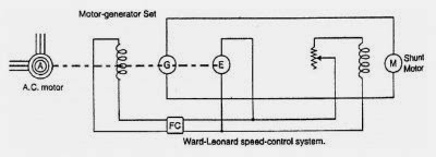
The armature of the shunt motor M (whose speed is to be controlled) is connected directly to a d.c. generator G driven by a constant-speed a.c. motor A.
The voltage of the generator G can be varied by means of its field regulator. By reversing the field current of generator G by controller Fc, the voltage applied to the motor may be reversed.
Sometimes, a field regulator is included in the field circuit of shunt motor M for additional speed adjustment. With this method, the motor may be operated at any speed upto its maximum speed.