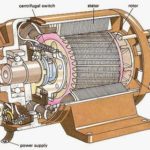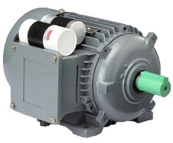
Single-phase motors are the most familiar of all-electric motors because they are extensively used in home appliances, shops, offices etc.
It is true that single-phase motors are a less efficient substitute for 3-phase motors but 3-phase power is normally not available except in large commercial and industrial establishments.
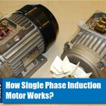
Working of Single Phase Induction motor
Unlike three-phase induction motors, single-phase induction motors are not self-starting. The reason behind this is very interesting.
Why Single Phase Induction Motor is Not Self Starting?
The single-phase induction motor has distributed stator winding and a squirrel-cage rotor.
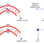
When fed from a single-phase supply, its stator winding produces a flux ( or field ) which is only alternating i.e. one which alternates along one space axis only.
It is not synchronously revolving ( or rotating ) flux as in the case of a two or a three-phase stator winding fed from a 2 of 3 phase supply.
Now, an alternating or pulsating flux acting on a stationary squirrel-cage rotor cannot produce rotation (only a revolving flux can produce rotation ). That is why a single phase motor is not self-starting.
However, if the rotor of such a machine is given an initial start by hand (or small motor) or otherwise in either direction, then immediately a torque arises and the motor accelerates to its final speed (unless the applied torque is too high).
This peculiar behavior of the motor has been explained using two theories below
- Two-field or double-field revolving theory
- Cross-field theory.
Only the double field revolving theory will be discussed briefly.
Double Field Revolving Theory
This theory makes use of the idea that an alternating uniaxial quantity can be represented by two oppositely rotating vectors of half magnitude.
So, an alternating sinusoidal flux can be represented by two revolving fluxes, each equal to half the value of alternating flux and each rotating synchronously in opposite directions.

As shown in Fig. (a), let the alternating flux have a maximum value of φm. It’s component fluxes A and B will each be equal to φm/2 revolving in anticlockwise and clockwise directions respectively.
After some time when A and B would have rotated through the angles +θ and –θ as in Fig (b), the resultant flux would be
After half a cycle, fluxes A and B will have a resultant of –2×(φm/2) = –φm.
If we plot the values of resultant flux against θ between limits θ=0° to θ=360°, then a curve similar to the one shown in the figure is obtained.

That is why an alternating flux can be looked upon as composed of two revolving fluxes each of half the value and revolving synchronously in opposite directions.
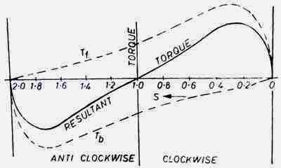
Each of the two-component fluxes while revolving around the stator cuts the rotor, induces an emf, and thus produces its own torque.
Obviously, the two torques (called forward and backward torques) are oppositely-directed so that the net or resultant torque is equal to their difference.
Hence, Tf and Tb are numerically equal but being oppositely directed, produce no resultant torque. That explains why there is no starting torque in a single-phase motor.
However, if the rotor is started somehow, say, in the clockwise direction, the clockwise torque starts increasing and, at the same time, the anticlockwise torque starts decreasing.
Hence, there is a certain amount of net torque in the clockwise direction which accelerates the motor to full speed.
How to Make Single Phase Induction Motor Self Starting?
As discussed above, single phase induction motors are not self-starting because a single phase supply cannot produce a rotating magnetic field. We require a two phase or three phase supply for the production of rotating magnetic field.
But we can create a rotating magnetic field by a two-phase construction.
So simply we can say in order to make a single phase induction motor self-starting, we have to temporarily convert it into a two-phase motor during its starting period.
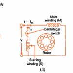
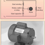
For this purpose, the stator of the single-phase induction motor is provided with an extra winding known as Starting or Auxillary Winding in addition to the Main or Running Winding.
The two winding are 90 degrees electrically displaced and are connected in parallel across the single phase supply.
It is so arranged that the phase difference between the currents in two stator windings ( main and running windings ) is very large ( ideal value is 90 degree ). Hence the motor behaves like a two-phase motor.
These two currents produce a revolving flux and hence make the motor self-starting.
The phase difference between the currents in the main winding and running winding can be obtained through different methods. The phase shift can be achieved by connecting a resistance, inductance or capacitance in series with the starting winding.
How Phase Shift is Created?
The difference between the current in starting winding and running winding in different single phase motors are created by different methods.
In this section, we will look into how the phase shift is created in each single phase motors.
Split Phase Induction Motor
In a split-phase induction motor the phase difference created by using windings of different resistance and reactance in the main winding and auxiliary winding.
Main winding (Running Winding): Low Resistance but High Reactance
Auxiliary Winding (Starting Winding): High Resistance and Low Reactance
Capacitor Start Induction Motors
Capacitor Start induction motors use a capacitor in series with the auxiliary winding to create a phase difference between the main winding and auxiliary winding.
Generally, an electrolytic type of capacitor is used for this function.