The dc generators and dc motors have the same general construction. In fact, when the machine is being assembled, the workmen usually do not know whether it is a dc generator or motor.
Any dc generator can be run as a dc motor and vice-versa. In this article, we will explain the construction of dc machine in detail.
Read: Working of DC Motor
All dc machines have the following principal components
- Magnetic frame or Yoke
- Pole Cores and Pole Shoes
- Pole Coils or Field Coils
- Armature core
- Armature Winding
- Commutator
- Brushes and Bearings
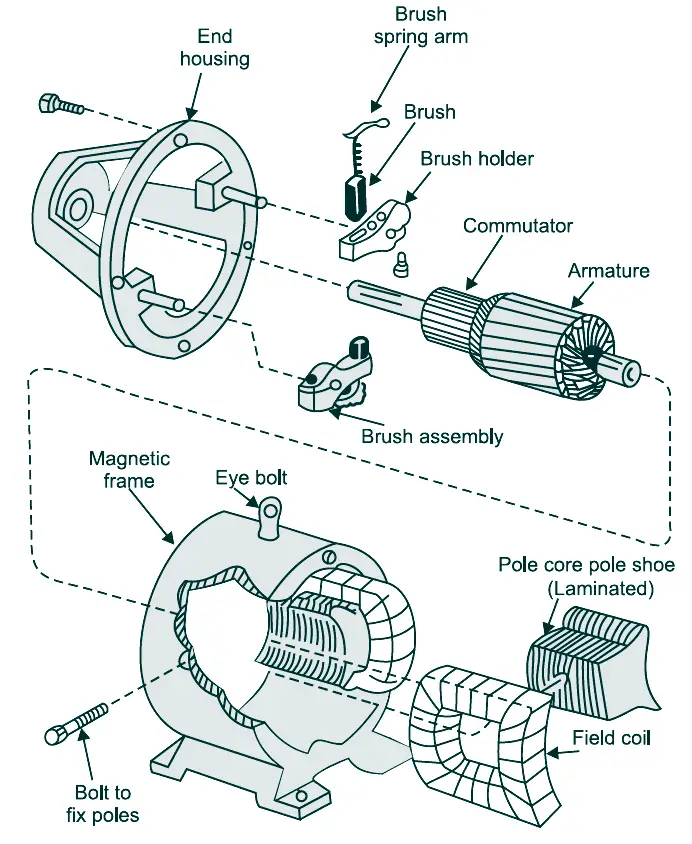
The diagram given below represents the various parts of a 2 pole DC machine.
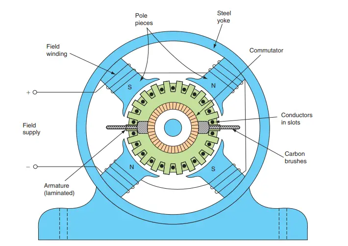
The cross-section of a four pole DC machine is shown in the figure below.

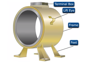
1. Yoke (Magnetic Frame)
The outer frame or yoke serves a double purpose :
- It provides mechanical support for the poles and acts as a protecting cover for the whole machine.
- It carries the magnetic flux produced by the poles.
In small generators where cheapness rather than weight is the main consideration, yokes are made of cast iron. But for large machines usually cast steel or rolled steel is employed.
The modern process of forming the yoke consists of rolling a steel slab around a cylindrical mandrel and then welding it at the bottom.
The feet and the terminal box etc. are welded to the frame afterward. Such yokes possess sufficient mechanical strength and have high permeability.
2. Pole Cores and Pole Shoes
The field magnets consist of pole cores and pole shoes. The pole shoes serve two purposes:
- they spread out the flux in the air gap and also, being of larger cross-section, reduce the reluctance of the magnetic path
- they support the exciting coils (or field coils)
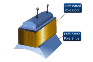
There are two main types of pole construction.
- The pole core itself may be a solid piece made out of either cast iron or cast steel but the pole shoe is laminated and is fastened to the pole face by means of countersunk screws
- In modern design, the complete pole cores and pole shoes are built of thin laminations of annealed steel which are riveted together under hydraulic pressure. The thickness of laminations varies from 1 mm to 0.25 mm.
3. Field system
The function of the field system is to produce a uniform magnetic field within which the armature rotates.
Field coils are mounted on the poles and carry the dc exciting current. The field coils are connected in such a way that adjacent poles have opposite polarity.
The m.m.f. developed by the field coils produces a magnetic flux that passes through the pole pieces, the air gap, the armature, and the frame.
Practical dc machines have air gaps ranging from 0.5 mm to 1.5 mm.
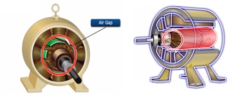
Since armature and field systems are composed of materials that have high permeability, most of the m.m.f. of field coils is required to set up flux in the air gap.
By reducing the length of the air gap, we can reduce the size of field coils (i.e. the number of turns).
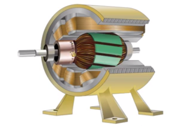
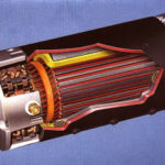
4. Armature core and Laminations
The armature core is keyed to the machine shaft and rotates between the field poles.
It consists of slotted soft-iron laminations (about 0.4 to 0.6 mm thick) that are stacked to form a cylindrical core as shown in the figure.
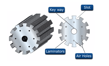
The laminations are individually coated with a thin insulating film so that they do not come in electrical contact with each other.
The purpose of laminating the core is to reduce the eddy current loss. Thinner the lamination, greater is the resistance offered to the induced e.m.f., smaller the current and hence lesser the I²R loss in the core.
The laminations are slotted to accommodate and provide mechanical security to the armature winding and to give a shorter air gap for the flux to cross between the pole face and the armature “teeth”.
5. Armature Winding
The slots of the armature core hold insulated conductors that are connected in a suitable manner. This is known as armature winding.

This is the winding in which “working” e.m.f. is induced. The armature conductors are connected in series-parallel; the conductors being connected in series so as to increase the voltage and in parallel paths so as to increase the current.
The armature winding of a dc machine is a closed-circuit winding; the conductors being connected in a symmetrical manner forming a closed-loop or series of closed loops.
Depending upon the manner in which the armature conductors are connected to the commutator segments, there are two types of the armature winding in a DC machine viz.,
- (a) lap winding
- (b) wave winding.
6. Commutator
A commutator is a mechanical rectifier which converts the alternating voltage generated in the armature winding into a direct voltage across the brushes.
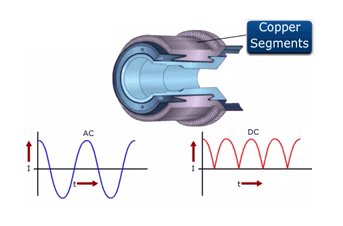
The commutator is made of copper segments insulated from each other by mica sheets and mounted on the shaft of the machine.
The armature conductors are soldered to the commutator segments in a suitable manner to give rise to the armature winding.
Depending upon the manner in which the armature conductors are connected to the commutator segments, there are two types of the armature winding in a DC machine viz.,
- Lap winding
- Wave winding.
Great care is taken in building the commutator because any eccentricity will cause the brushes to bounce, producing unacceptable sparking.
The sparks may bum the brushes and overheat and carbonize the commutator.
7. Brushes
DC motors are of two types: one is a brushed dc motor and the other one is brushless dc motor. Brushless dc motors are mainly used in high-speed applications such as multicopters (eg:- quadcopters).
The purpose of brushes in a dc generator is to ensure electrical connections between the rotating commutator and stationary external load circuit.
The brushes are made of carbon and rest on the commutator. The brush pressure is adjusted by means of adjustable springs.
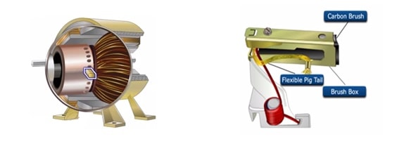
If the brush pressure is very large, the friction produces heating of the commutator and the brushes.
On the other hand, if it is too weak, the imperfect contact with the commutator may produce sparks. Multipole machines have as many brushes as they have poles. For example, a 4-pole machine has 4 brushes.
As we go round the commutator, the successive brushes have positive and negative polarities.
Brushes having the same polarity are connected together so that we have two terminals viz., the +ve terminal and the -ve terminal
Key Points
Type of material used for the construction of the DC machine:
| Yoke | Small Machine: Cast IronLarge Machine: Cast steel |
| Pole core and pole shoe | Annealed steel |
| Armature core | Laminated steel |
| Commutator | Hard drawn copper |
| Brushes (small machine) | Copper or Carbon |
| Brushes (normal and large machine) | Electro – graphite |
Video: Construction of DC Generator
Watch the video below to understand the construction of dc generator and dc motor.
Comments are closed.