Armature reaction in alternator is the effect of armature flux on the field flux (i. e., rotor ampere-turns). Read this article to learn more.
We have already discussed the effect of armature reaction on the air gap flux in DC Motor and DC Generator in previous articles. Similarly, armature reaction has effect on the air gap flux in case of the alternator also.
We know that when current flows through armature conductors it gives rise to magnetic flux encircling these conductors and hence this certainly will affect the distribution of flux in the air gap due to the rotor flux.
When an alternator is running at no-load, there will be no current flowing through the armature winding. The flux produced in the air-gap will be only due to the rotor ampere-turns.
When the alternator is loaded, the three-phase currents will produce a totaling magnetic field in the air-gap. Consequently, the air-gap flux is changed from the no-load condition.
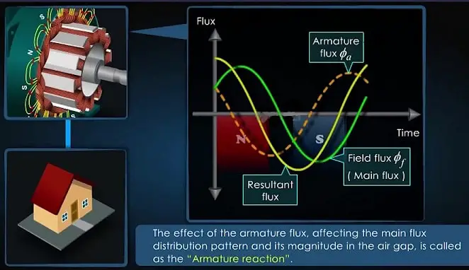
The effect of armature flux on the flux produced by field ampere-turns (i. e., rotor ampere-turns) is called armature reaction in an alternator.

Firstly, the armature flux and the flux produced by rotor ampere-turns rotate at the same speed (synchronous speed) in the same direction and, therefore, the two fluxes are fixed in space relative to each other.
Secondly, the modification of flux in the air-gap due to armature flux depends on the magnitude of stator current and on the power factor of the load.
It is the load power factor which determines whether the armature flux distorts, opposes or helps the flux produced by rotor ampere-turns.
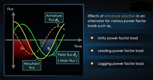
To illustrate this important point, we shall consider the following three cases:
- When the load power factor is unity
- When the load power factor is zero lagging
- When the load power factor is zero leading
Armature Reaction in Alternator When Load Power Factor is Unity

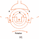
Figure (i) shows an elementary alternator on no load. Since the armature is on open-circuit, there is no stator current and the flux due to rotor current is distributed symmetrically in the air-gap as shown in Fig. (i).
Since the direction of the rotor is assumed clockwise, the generated e.m.f. in phase R1R2 is at its maximum and is towards the paper in the conductor R1 and outwards in conductor R2. No armature flux is produced since no current flows in the armature winding.
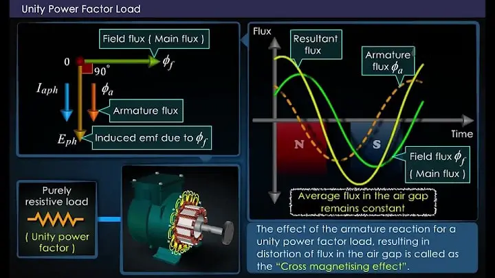
Figure (ii) shows the effect when a resistive load (unity p.f.) is connected across the terminals of the alternator. According to the right-hand rule, the current is “in” in the conductors under N-pole and “out” in the conductors under S-pole.
Therefore, the armature flux is clockwise due to currents in the top conductors and anti-clockwise due to currents in the bottom conductors.
Note that armature flux is at 90° to the main flux (due to rotor current) and is behind the main flux. In this case, the flux in the air-gap is distorted but not weakened.
Therefore, at unity p.f., the effect of armature reaction is merely to distort the main field. There is no weakening of the main field and the average flux practically remains the same.
Since the magnetic flux due to stator currents (i.e., armature flux) rotate; synchronously with the rotor, the flux distortion remains the same for all positions of the rotor.
Armature Reaction in Alternator When Load Power Factor is Zero Lagging

When a purely inductive load (zero p.f. lagging) is connected across the terminals of the alternator, current lags behind the voltage by 90°. This means that current will be maximum at zero e.m.f. and vice-versa. Fig. (i) shows the condition when the alternator is supplying resistive load. Note that e.m.f. as well as current in phase R1R2 is maximum in the position shown.
When the alternator is supplying a purely inductive load, the current in phase R1R2 will not reach its maximum value until N-pole advanced 90° electrical as shown in Fig (ii).
Now the armature flux is from right to left and field flux is from left to right.
All the flux produced by armature current (i.e., armature flux) opposes be field flux and, therefore, weakens it. In other words, the armature reaction is directly demagnetizing.
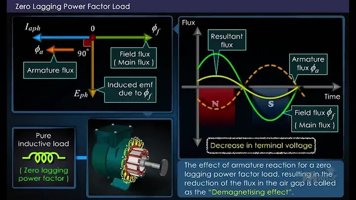
Hence at zero p.f. lagging, the armature reaction weakens the main flux. This causes a reduction in the generated e.m.f.
Armature Reaction in Alternator When Load Power Factor is Zero Leading
When a pure capacitive load (zero p.f. leading) is connected across the terminals of the alternator, the current in armature windings will lead the induced e.m.f. by 90°.

Obviously, the effect of armature reaction will be the reverse that for pure inductive load. Thus armature flux now aids the main flux and the generated e.m.f. is increased.
Fig (i) shows the condition when the alternator is supplying a resistive load.
Note that e.m.f. as well as current in phase R1R2 is maximum in the position shown. When the alternator is supplying a pure capacitive load, the maximum current in R1R2 will occur 90° electrical before the occurrence of maximum induced e.m.f.
Therefore, the maximum current in phase R1R2 will occur if the position of the rotor remains 90° behind as compared to its position under resistive load. This is illustrated in Fig (ii).
It is clear that armature flux is now in the same direction as the field flux and, therefore, strengthens it. This causes an increase in the generated voltage.
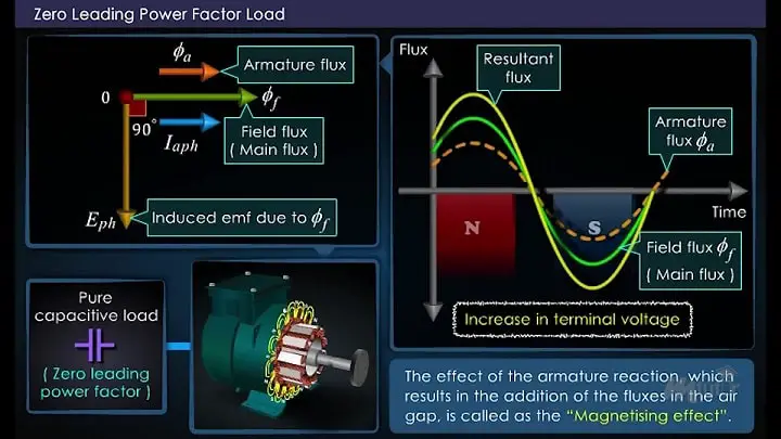
Hence at zero p.f. leading, the armature reaction strengthens the main flux.
Conclusion
For intermediate values of power factor, the effect of armature reaction is partly distorting and partly weakening for inductive loads.
For capacitive loads, the effect of armature reaction is partly distorting and partly strengthening.
In practice, loads are generally inductive. Hence in practical condition, the effect of armature reaction in the alternator is partly distorting and partly weakening.


Comments are closed.