No electronics can run without power, to be precise a low voltage DC power, and a power supply unit is a device which is specifically meant for fulfilling this purpose.
Here we cover complete details on how to design a power supply unit. We start with simple circuits and then proceed to complex circuits so that any newbie can understand the concepts very easily.
Main Components of a Power Supply Circuit
There are four main components in a power supply circuit.
Transformer
Rectifier (Diode)
Filter (Capacitor)
Voltage Regulator
The transformeris one of the main components in a power supply circuit because we need to convert the higher voltage available in the power point into a lower voltage we needed. For example, if the transformer secondary is rated at 12 volts then the acquired 12 volts from the transformer secondary will be a 12 volt AC across the relevant wires.
The electronic circuit can never work with ACs and therefore this voltage should be transformed into a DC. The function of the diode used in the circuit is to rectify the AC output from the transformer to DC. The low voltage AC available at the transformer output will be rectified by the diode.
The capacitoris used as a filter to remove the ripples from the rectified DC signal. Ripples mean AC components in the DC signal. Capacitor filters those AC components and provides a stable DC. 50V 1000uF, 25V 1000uF or 35V 1000uF capacitors can be used for this purpose.
The voltage regulator provides the regulated output. There are many voltage regulator ICs available in the market. For 5V dc output we can use LM7805, for 9 V dc power supply we can use LM7809 and for 12V dc power supply LM7812 can be used.
Diode Configurations
A diode is a device which effectively converts AC to DC. There are three configurations through which basic power supply designs may be configured.
Using Single Diode
Using Two Diodes
Using 4 Diodes
Power Supply Circuit Using Single Diode
This is the most basic form of power supply design which uses a single diode and a capacitor.
Since a single diode will rectify only one-half cycle of the AC signal, this type of configuration requires a large output filter capacitor for compensating the above limitation.
Power supply using a single diode
A filter capacitor makes sure that after rectification, at the falling or decreasing sections of the resultant DC pattern, where the voltage tends to dip, these sections are filled and topped by the stored energy inside the capacitor.
The above compensation act done by the capacitors stored energy helps to maintain a clean and ripple free DC output which wouldn’t be possible just by the diodes alone.
For a single diode power supply design, the transformer’s secondary winding just needs to have a single winding with two ends.
However, the above configuration cannot be considered an efficient power supply design due to its crude half wave rectification and limited output conditioning capabilities.
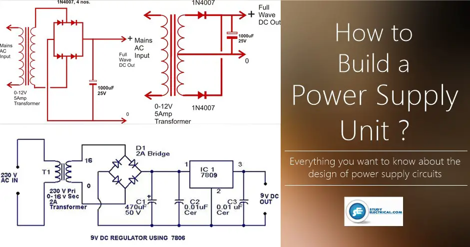
Power Supply Circuit Using Two Diodes
Power Supply using two diodes
Using a couple of diodes for making a power supply requires a transformer having a center tapped secondary winding. The diagram shows how the diodes are connected to the transformer.
Though, the two diodes work in tandem and tackle both the halves of the AC signal and produce a full wave rectification,
This method is not efficient, because at any instant only one-half winding of the transformer is utilized.
This results in poor core saturation and unnecessary heating of the transformer, making this type of power supply configuration less efficient and ordinary design.
Power Supply Circuit Using Four Diodes
It’s the best and universally accepted form of power supply configuration as far as the rectification process is concerned. This type of diode configuration is popularly known as the bridge network
The clever use of four diodes makes things very simple, only a single secondary winding is all that is required, the core saturation is perfectly optimized resulting in an efficient AC to DC conversion.
Power supply design using four diodes
The figure shows how a full wave rectified power supply is made using four diodes and a relatively low value filter capacitor.
All the above power supply designs provide outputs with ordinary regulation and therefore cannot be considered perfect. They fail to provide ideal DC outputs, and therefore are not desirable for many sophisticated electronic circuits.
Moreover, these configurations does not include a variable voltage and current control features. However the above problems can be overcome through the use of a single IC and a few other passive components in those designs.
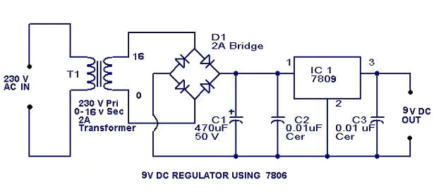
9 V regulator using 7809
Here is the circuit diagram of 9 V regulator using popular 7809 IC.
9V Regulator power supply circuit diagram
The 7809 is a 9 Volt voltage regulator IC with features such as internal current limit, safe area protection, thermal protection etc. A 16 V transformer brings down the 230V mains, 1A bridge rectifier rectifies it and capacitor C1 filters it and 7809 regulates it to produce a steady 9V DC output.
If a current of 300 mA or above is required, fit a proper heat sink to the IC 7809. If 1A bridge is not available, make one using four 1N 4007 diodes.