What is a Static Relay?
There are two basic classifications of relays – Electromechanical Relays and Solid State Relays (Static relay). One main difference between them is electromechanical relays have moving parts, whereas solid-state relays have no moving parts.
Solid State Relay (Static Relay) is an electrical relay in which the response is developed by electronic/magnetic/optical or other components, without mechanical motion of components.
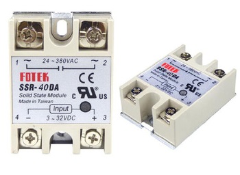
A solid state relay is composed of both static and electromechanical units in which the response is accomplished by the static units. Therefore solid state relays are also called as static relays.
In static relays, the measurement is performed by electronic/magnetic/optical or other components without mechanical motion. However additional electromechanical relay units may be used in output stage as auxiliary relays. A protective system is formed by static relays and electromechanical auxiliary relays.
Working of Solid State Relay

The output of the measuring unit is amplified by Amplifier. The amplified output is given to the output unit which energizes the trip coil only when the relay operates.
In conventional electromagnetic, the measurement is carried out by comparing operating torque/force with restraining torque/force. The electro-mechanical relay operates when operating torque/fence exceeds the restraining torque/force. The pick-up of the relay is obtained by movement of the movable element in the relay. In a static relay, the measurement is performed by static councils.
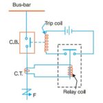
A simplified block diagram of a single input static relay is given in the above figure. In individual relays, there is a wide variation. The quantities: voltage, current. etc. is rectified and measured. When the quantity to be measured reaches certain well-defined value, the output device is triggered. Thereby current flows in the trip circuit of the circuit-breaker.
The figure below gives a block diagram of a microprocessor-based digital, programmable static relay.

Static relays can be arranged to respond to electrical inputs. The other forms of inputs such as heat, light, magnetic field, traveling waves, etc. can be suitably converted into equivalent analog or digital signals and then fed to the static relay.
The multi-input static relay can accept several inputs. The logic circuit in the multi-input digital static relay can determine the conditions for relay response and sequence of events in the response.
A programmable protection and control system has a microprocessor or microcomputer in its circuit.
With the help of the logic circuits and the microprocessor, the integrated protection and control system can perform several functions of data acquisition, data processing, data transmission, protection, and control. Earlier, for each of these functions, separate electromechanical or static units were used along with complex wiring.


Comments are closed.