 We have already given an introduction to substation earthing system in an article published earlier. Today we are going to discuss the design of substation earthing system.
Before 1960s the design criterion of substation earthing system was “low earth resistance.” (Earth Resistance< 0.5 ohms for High Voltage installations).
During the 1960s, the new criteria for the design and evaluation of Substation Earthing System were evolved particularly for EHV AC and HVDC Substations.
The new criteria are :
- Low Step Potential
- Low Touch Potential
- Low Earth Resistance.
The conventional “Low earth resistance criterion” and Low Current Earth Resistance Measurement continues to be in practice for Substations and Power Station up to and including 220 kV.
The parts of the Earthing System include the entire solid metallic conductor system between various earthed points and the underground earth-mat.
The earthed points are held near-earth potential by low resistance conductor connections with earth-mat.
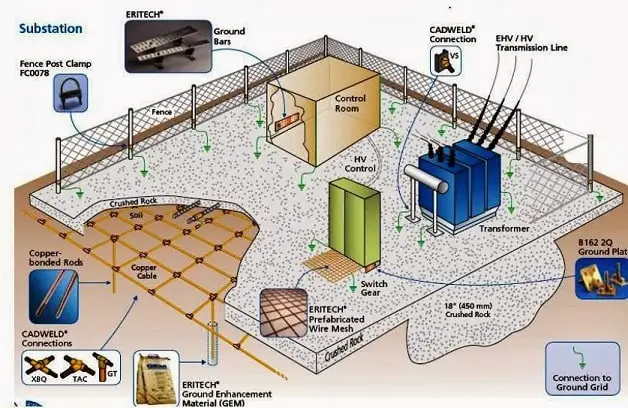
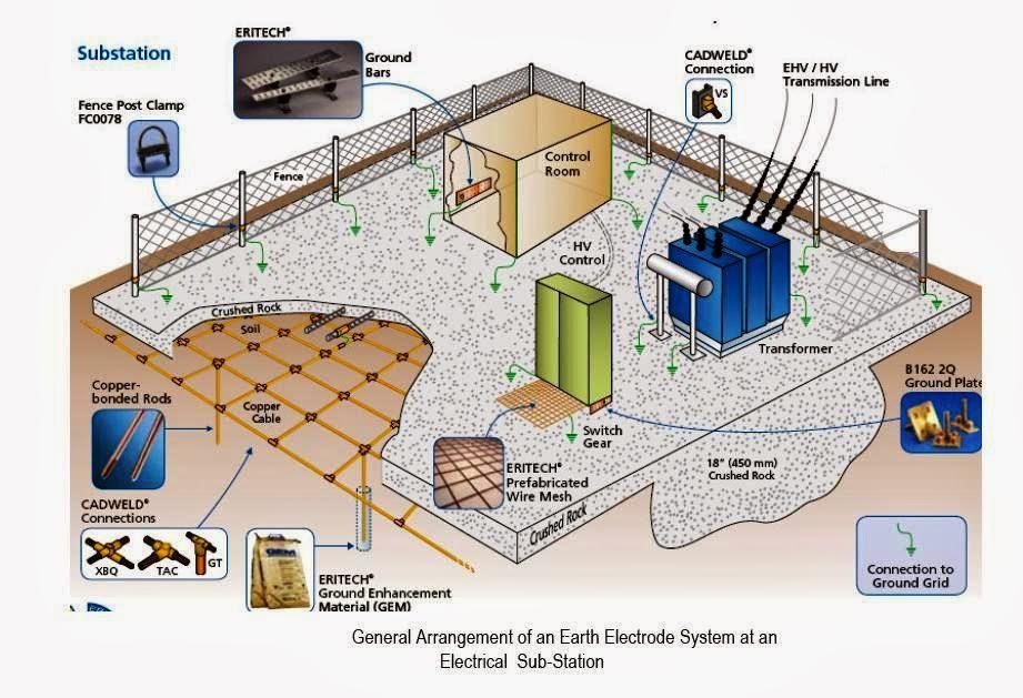
Substation Earthing System Design
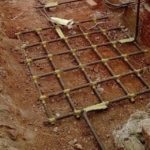
Underground Horizontal Earth Mesh (Mat/Grid)
The crossings of the horizontal bars in X and Y directions are welded.
The mesh ensures uniform and zero potential distribution on the horizontal surface of the floor of the substation hence low “step potential” in the event of flow of earth fault current.

Earthing Electrodes (Spikes)
- The number of Earth-Electrodes (Spikes) Ns for soil resistivity 500-ohm meter and earth fault current Is is :
Ns = Is / 250 Amperes
- The number of Earth-Electrodes (Spikes) Ns for soil resistivity 5000-ohm meter is
Ns = Is / 500 Amperes
33 kV substations: 25000 to 31000 A
400 kV Substations: 40000 A
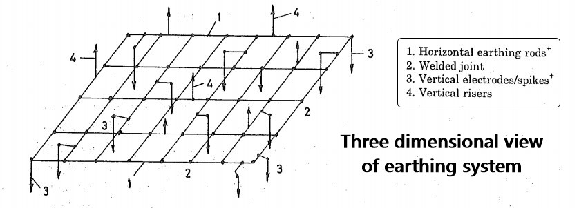
Earthing Risers
Earthing Connection
For Transformer Neutral/High Current Discharge paths copper strips/stranded wires are preferred.
The earthing strips are finally welded or bolted or clamped to the Earthed Point.


Comments are closed.