The percentage impedance ($\%Z$) of a transformer is one of the most vital figures stamped on the nameplate of every power and distribution transformer in electrical substations.
Whether you are performing short-circuit fault calculations, sizing protective switchgear, calculating voltage drop, or planning parallel operation, understanding $\%Z$ is essential.
In this guide, we break down what percentage impedance means, how it is measured, step-by-step calculation formulas, real-world examples, and its exact role in power system engineering.
What is Percentage Impedance?
The impedance of a transformer represents the total opposition offered by its windings to alternating current ($AC$). While impedance can technically be calculated for each winding separately, a simple practical test allows us to measure the equivalent impedance of the entire transformer without separating the primary and secondary windings.
When engineers refer to the impedance of a transformer, they mean this equivalent impedance.
Definition of Percentage Impedance
The percentage impedance ($\%Z$) of a transformer is defined as the internal voltage drop at full load due to winding resistance and leakage reactance, expressed as a percentage of the rated normal voltage.
In other words: It is the percentage of rated primary voltage required to circulate full-load rated current through the windings when the secondary side is short-circuited.
📌 Key Concept: If an $11\text{ kV} / 415\text{ V}$ transformer has a percentage impedance of $5\%$, applying just $5\%$ of $11\text{ kV}$ ($550\text{ V}$) to the primary while the secondary is short-circuited will cause full-load rated current to flow in both windings.
Detailed Explanation of Percentage Impedance
If you apply full rated voltage to the primary winding while the secondary winding is short-circuited, an extremely high current will flow. This is called the short-circuit current ($I_{SC}$), and its magnitude is dangerous because the shorted load offers almost zero impedance.
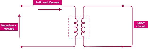
⚡ Quick Concept: Impedance Voltage
- 🔴 Full Rated Voltage + Shorted Secondary ⚡ Extreme Fault Current
- 🟢 Reduced Voltage (%V) + Shorted Secondary ⚡ Rated Full-Load Current
💡 The reduced voltage percentage that produces full-load current IS the Percentage Impedance (%Z).
To prevent damage during transformer testing:
- The applied primary voltage is significantly reduced.
- As you gradually increase the primary voltage from $0\text{ V}$, the current in both windings increases proportionally.
- At a specific fraction of the rated voltage, rated full-load current will circulate through the windings.
- This specific fraction of the rated voltage is called the impedance voltage, and when expressed as a percentage of full primary voltage, it gives the percentage impedance ($\%Z$).
How to Test and Calculate Percentage Impedance
To determine equivalent impedance in a lab or manufacturing plant, a Short-Circuit Test is performed:
- Short Circuit the LV Side: Either winding can be shorted, but it is standard and more convenient to short-circuit the low-voltage (LV) winding.
- Apply Voltage on HV Side: Just enough AC voltage is applied to the high-voltage (HV) winding to cause full-load current to flow in the shorted circuit.
- Record Impedance Voltage ($V_{SC}$): The applied voltage reading is recorded.
(Want to learn more about this procedure? Read our full guide on How to Test the Percentage Impedance of a Transformer.)
Formulas for Percentage Impedance Calculation
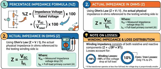
1. Percentage Impedance Formula
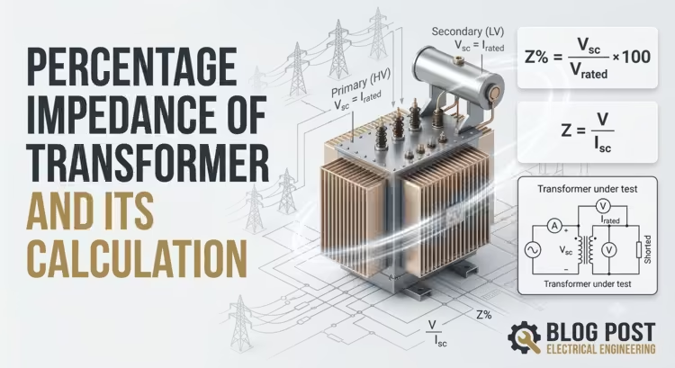
$$\%Z = \left( \frac{\text{Impedance Voltage}}{\text{Rated Voltage}} \right) \times 100 = \left( \frac{V_{SC}}{V_{\text{rated}}} \right) \times 100$$
2. Actual Impedance in Ohms ($Z$)
Using Ohm’s Law ($Z = \frac{V}{I}$), the actual physical impedance in ohms referenced to the testing winding side is:
$$Z = \frac{V_{SC}}{I_{FL}}$$
Where:
- $V_{SC}$ = Measured impedance voltage drop ($V$)
- $I_{FL}$ = Full-load primary current ($A$)
💡 Note on Losses: Winding impedance consists of both resistive and reactive components ($Z = \sqrt{R^2 + X^2}$). Winding losses account for approximately $98\%$ of this voltage drop at full load, while core/iron losses account for only $1\%$ to $2\%$. If the transformer operates at less than full load, the voltage drop is proportionally smaller.
What is Per-Unit Impedance ($Z_{pu}$)?
In power system calculations, engineers often convert percentage impedance into per-unit impedance ($Z_{pu}$).
While percentage impedance expresses the impedance voltage drop as a percentage out of $100$, per-unit impedance expresses the exact same ratio as a decimal fraction out of $1.0$.
Relationship Formula
$$Z_{pu} = \frac{\%Z}{100}$$
$$\%Z = Z_{pu} \times 100$$
Example: If a transformer has a percentage impedance of $5\%$, its per-unit impedance is $0.05\text{ pu}$.
Difference Between Percentage Impedance ($\%Z$) and Per-Unit Impedance ($Z_{pu}$)
| Feature / Property | Percentage Impedance (%Z) | Per-Unit Impedance (Zpu) |
| Base Scale | Scaled out of $100\%$ | Scaled out of $1.0\text{ pu}$ |
| Typical Usage | Stamped on physical transformer nameplates and factory test reports | Used in power system fault calculations, single-line diagrams, and software simulations |
| Why Use It? | Easy to read and standardize during manufacturing | Prevents scaling errors when solving multi-voltage networks |
When solving complex multi-voltage power network calculations, converting all equipment impedances to the per-unit system allows engineers to analyze the network as a single continuous electrical circuit without worrying about turns ratios at every transformer boundary.
Step-by-Step Example Calculations of Z%
Example 1: Calculating $\%Z$ and Impedance in Ohms
Problem: A $2400\text{ V} / 240\text{ V}$ transformer has a measured impedance voltage ($V_{SC}$) of $72\text{ V}$ on the high-voltage winding, and its full-load primary current ($I_{FL}$) is $10\text{ A}$.
- Calculate $\%Z$:$$\%Z = \left( \frac{72\text{ V}}{2400\text{ V}} \right) \times 100 = 3\%$$
- Calculate Impedance in Ohms ($Z$):$$Z = \frac{V_{SC}}{I_{FL}} = \frac{72\text{ V}}{10\text{ A}} = 7.2\ \Omega$$
Interpretation: There is a $72\text{ V}$ drop in the high-voltage winding at full load due to winding and core impedance.
Example 2: Calculating Maximum Symmetrical Short-Circuit Fault Level
Problem: Consider a $2\text{ MVA}$ transformer with a percentage impedance of $5\%$. Calculate the maximum fault MVA available on the secondary side.
$$\text{Maximum Fault Level (MVA)} = \text{Rating (MVA)} \times \left( \frac{100}{\%Z} \right)$$
$$\text{Maximum Fault Level} = 2\text{ MVA} \times \left( \frac{100}{5} \right) = 40\text{ MVA}$$
From this $40\text{ MVA}$ symmetrical fault level, protection engineers can easily calculate the equivalent primary and secondary short-circuit fault currents.
Factors Influencing $\%Z$ during Design
The core and winding construction creates a “natural” impedance value determined primarily by leakage flux.
Leakage flux is governed by:
- The ampere-turns of the windings.
- The physical length and surface area of the leakage flux path.
Transformer designers intentionally vary $\%Z$ during the design phase by altering the volts-per-turn ratio and adjusting the geometric physical spacing between the primary and secondary windings.
Role of Percentage Impedance in Power Systems
| Feature / Consideration | High Percentage Impedance (%Z) | Low Percentage Impedance (%Z) |
| Short-Circuit Current ($I_{SC}$) | Lowers fault current levels | Increases short-circuit current levels |
| Mechanical Stress on Insulation | Lower stress during faults | Higher electromagnetic stress on insulation |
| Voltage Regulation | Higher internal voltage drop (Poorer regulation) | Lower internal voltage drop (Better regulation) |
| Switchgear Requirements | Lower breaking capacity required | Heavy-duty circuit breakers needed |
1. Short-Circuit Fault Calculations
The short-circuit current ($I_{SC}$) that flows during a symmetrical fault is directly calculated using $\%Z$:
$$I_{SC} = I_{\text{rated}} \times \left( \frac{100}{\%Z} \right)$$
- Although $\%Z$ remains identical for both sides, the rated currents ($I_{\text{rated}}$) for the primary and secondary windings are different. Thus, the actual short-circuit current values in amperes will differ between primary and secondary sides.
- Trade-off: A lower $\%Z$ improves voltage regulation (positive), but increases short-circuit current during a fault, producing extreme thermal and mechanical stress on insulation (negative). $\%Z$ must be precisely selected to balance fault limits and voltage stability.
2. Parallel Operation of Transformers
Percentage impedance has a major role when operating transformers in parallel. For two transformers connected in parallel to share total load correctly:
$$\frac{\text{kVA}_1}{\%Z_1} = \frac{\text{kVA}_2}{\%Z_2}$$
- If the ratio of kVA rating to percentage impedance is equal, they share load proportionally.
- If percentage impedances are unequal, the transformer with the lower $\%Z$ will draw a disproportionately higher share of the load, causing it to overheat and potentially trip.
Permitted Manufacturing Tolerances in $\%Z$ (IEC 60076)
While a specific $\%Z$ is requested when ordering a transformer, international standards recognize manufacturing variations.
According to IEC 60076, a tolerance of $\pm 10\%$ on percentage impedance is permitted at the manufacturer’s end:
$$\text{Actual } \%Z = \text{Specified } \%Z \pm 10\%$$
⚠️ Practical Example: If you order a transformer with an $8\%$ target impedance, the manufactured unit’s actual nameplate impedance can legally be anywhere between $7.2\%$ ($-10\%$) and $8.8\%$ ($+10\%$).
System engineers must account for these worst-case tolerance limits when calculating protection settings, fault levels, and busbar interrupting capabilities.
Frequently Asked Questions (FAQs)
Is percentage impedance the same on the primary and secondary sides?
Yes. Percentage impedance ($\%Z$) is a dimensionless ratio. Whether calculated using primary voltage and primary full-load current or secondary voltage and secondary full-load current, the resulting percentage value remains identical.
Can percentage impedance be changed after a transformer is installed?
No. Percentage impedance is fixed during manufacturing based on core design, physical winding dimensions, distance between windings, and turn count. It cannot be altered without adding external series reactors or modifying internal windings.