Please read Ideal Transformer and Practical Transformer before continuing.
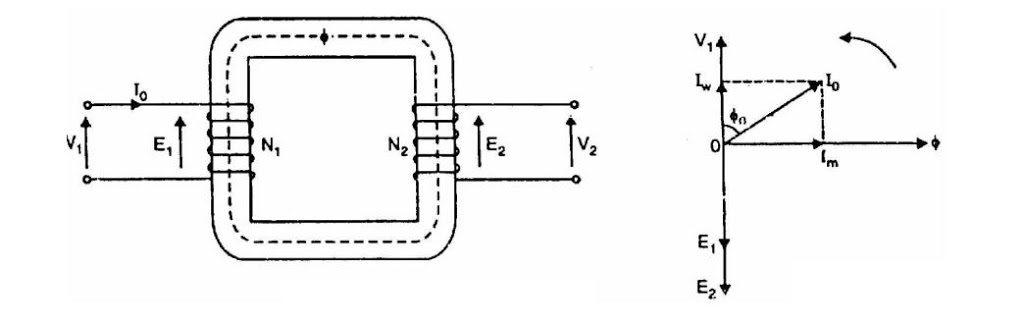
Consider a practical transformer on no load i.e., secondary on open-circuit as shown in figure below.
Consider a practical transformer on no load i.e., secondary on open-circuit as shown in figure below.
The primary will draw a small current I0 to supply
(i) the iron losses and
(ii) a very small amount of copper loss in the primary.
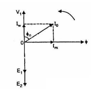
Hence the primary no load current I0 is not 90° behind the applied voltage V1 but lags it by an angle Φ0 < 90° as shown in the phasor diagram.
No load input power, W0 = V1 I0 cosΦ0
As seen from the phasor diagram, the no-load primary current I0 can be resolved into two rectangular components viz.
- Iw
- Im
(i) The component Iw in phase with the applied voltage V1. This is known as active or working or iron loss component and supplies the iron loss and a very small primary copper loss.
Iw = I0 cosΦ0
(ii) The component Im lagging behind V1 by 90° and is known as magnetizing component. It is this component which produces the mutual flux Φ in the core.
Im = I0 sinΦ0
Clearly, I0 is phasor sum of Im and Iw.
I0 = √ (Im2 +Iw2)
No load power factor, cosΦ0 = Iw∕I0
It is emphasized here that no load primary copper loss (i.e. I02R1 ) is very small and may be neglected. Therefore, the no load primary input power is practically equal to the iron loss in the transformer i.e.,
No load input power, W0 = Iron loss
Note.
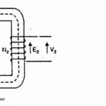
At no load, there is no current in the secondary so that V2 = E2.
On the primary side, the drops in R1 and X1, due to I0 are also very small because of the smallness of I0.
Hence, we can say that at no load, V1 = E1.


this web site is
in fact excellent.