DC generators have been fundamental in the history of electrical power generation. Yet, behind their seemingly simple operation lies a crucial phenomenon: armature reaction. This article unveils the significance of armature reaction in DC generators, shedding light on its effects and how engineers manage it for optimal performance. Join us on this exploration of an often overlooked but essential aspect of electrical engineering.
To understand the concept of armature reaction in DC generator, you should have a good understanding on the construction of DC generator.
The Basics of DC Generators
Direct Current (DC) generators, though often overshadowed by their alternating current (AC) counterparts in modern power systems, hold a rich history and continue to find application in various industries. To understand armature reaction in DC generators, we first need to grasp the fundamental principles that govern their operation.
Explanation of DC Generator Operation
DC generators, also known as dynamos, are devices designed to convert mechanical energy into direct current electrical power. The core principle behind their operation is electromagnetic induction, as discovered by Michael Faraday in the early 19th century. When a conductor, such as a wire loop, moves within a magnetic field, it generates an electromotive force (EMF) or voltage across its terminals. This phenomenon forms the basis of DC generator operation.
Components of a DC Generator
DC generators consist of several key components, each playing a specific role in the generation of electricity:
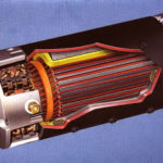
- Armature: The armature is a core component that rotates within the magnetic field. It typically consists of multiple wire loops or coils connected to the output terminals.
- Field Magnets: The field magnets establish a powerful magnetic field within which the armature rotates. These magnets can be either permanent magnets or electromagnets, depending on the generator type.
- Commutator: The commutator is a split ring attached to the armature shaft, and it plays a crucial role in converting alternating current induced in the armature into direct current.
- Brushes: Brushes are stationary carbon or graphite contacts that press against the commutator, providing an electrical connection between the rotating armature and the external circuit.
Role of the Armature in Generating Electricity
The armature, in particular, is the heart of a DC generator. As it rotates within the magnetic field, it experiences changes in magnetic flux, leading to the generation of an induced electromotive force (EMF) or voltage. This induced voltage, however, is alternating in nature due to the changing direction of the magnetic flux as the armature rotates.
To convert this alternating voltage into direct current, DC generators employ a commutator and brushes. The commutator reverses the direction of current flow in the armature coils at the precise moment when it changes direction, resulting in a unidirectional or direct current at the output terminals.
Understanding the operation of DC generators is fundamental to comprehending armature reaction, a phenomenon closely tied to the interaction between the armature’s magnetic field and the field magnets. In the following sections, we will dive deeper into this interaction and how it impacts generator performance.
What is Armature Reaction?
There are two windings in a dc generator and a dc motor:
- Field winding
- Armature Winding.
The purpose of field winding is to produce a magnetic field (called main flux) whereas the purpose of armature winding is to carry armature current.
Although the armature winding is not provided for the purpose of producing a magnetic field, still the current in the armature winding also produces a magnetic flux (called armature flux).
The armature flux distorts and weakens the main flux and create problems for the proper operation of the dc machines.
The action of armature flux on the main flux is called armature reaction in a dc generator.
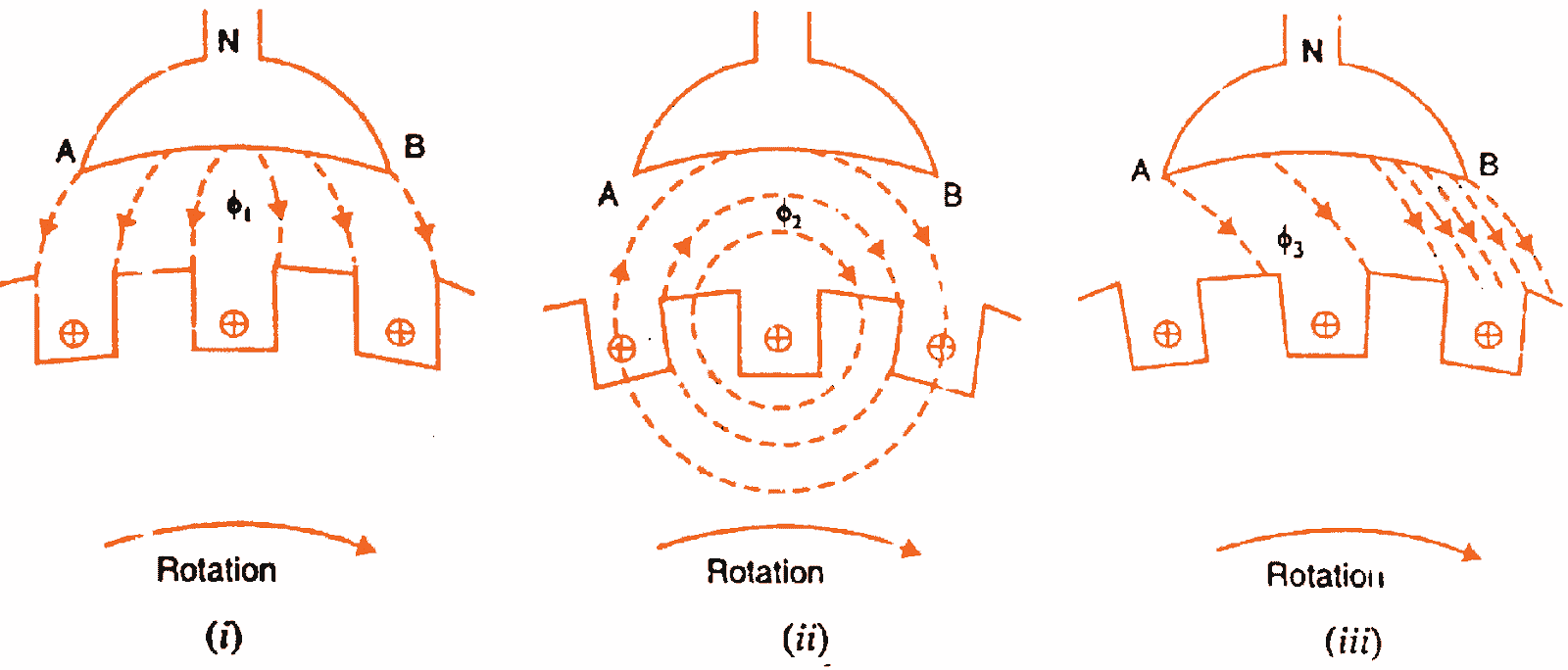
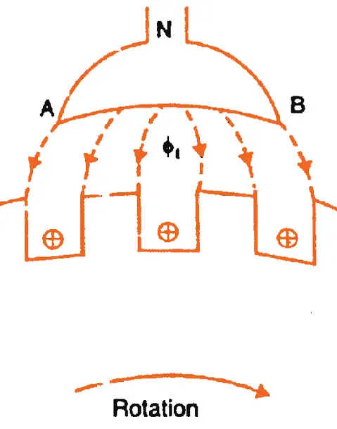
The phenomenon of armature reaction in a dc generator is shown in the figure below. For the sake of clarity, we are taking only one pole.
When the generator is on no-load , a small current is flowing through the armature and therefore flux produced in the armature is very small and it does not affect the main flux φ1 coming from the pole.
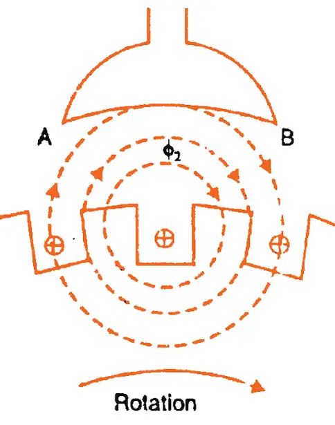
When the generator is loaded, high current start flowing through the armature conductors, thus a high flux φ2 is set up as shown below.
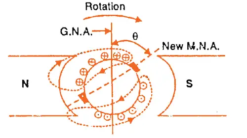
By superimposing the fluxes φ1 and φ2, we obtain the resulting flux φ3 as shown below. This is what happens to the flux under one pole under armature reaction in a dc generator.
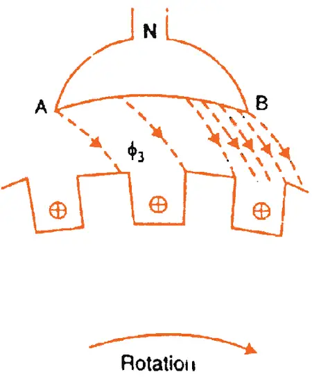
From the above figure it is clear that flux density at the trailing pole tip (point B) is increased while at the leading pole tip (point A) it is decreased.
This unequal field distribution due to the armature reaction in dc generator produces the following two effects:
- The main flux is distorted. (Cross magnetization)
- The main Flux is weakened. (Demagnetization)
The weakening of flux due to armature reaction in a dc generator also depends on the position of the brushes. For that, we need to understand the geometrical and magnetic neutral axes.
In short armature reaction occurs as a consequence of the armature current flowing through the coils of the generator’s armature. As this current flows, it generates its own magnetic field, which adds to or opposes the existing magnetic field produced by the field magnets. The result is a distortion of the overall magnetic field within the generator.
This distortion can lead to several important effects:
- Flux Weakening: In some cases, the armature current can weaken the net magnetic field strength experienced by the armature, reducing the generator’s output voltage.
- Shift in Neutral Plane: The neutral plane, which is a point where the induced voltage in the armature coil is zero, can shift from its ideal position. This shift affects the commutation process, potentially causing sparking and brush wear.
- Voltage Regulation: Armature reaction can impact the generator’s ability to maintain a constant output voltage, especially under varying load conditions.
Geometrical and Magnetic Neutral Axes
The geometrical neutral axis and magnetic neutral axis should be clearly understood in order to get a clear idea of armature reaction in a dc generator.
The geometrical neutral axis (GNA) is the axis that bisects the angle between the center line of adjacent poles.

The magnetic neutral axis (MNA) is the axis drawn perpendicular to the mean direction of the flux passing through the center of the armature.
No e.m.f. is produced in the armature conductors along this axis because then they cut no flux. When no current is there in the armature conductors, the MNA coincides with GNA.
Explanation of Armature Reaction
The armature reaction in a dc generator is explained as below. Consider no current in armature conductors, then MNA coincides with GNA.
Now, when current start flowing through the armature conductors, due to the combined action of main flux and armature flux the MNA get shifted from GNA.
In case of a generator, the M.N.A. is shifted in the direction of rotation of the machine. In order to achieve sparkless commutation, the brushes should be moved along the new MNA.
Under such a condition, the armature reaction in a dc generator produces the following two effects:
- It demagnetizes or weakens the main flux.
- It cross-magnetizes or distorts the main flux.
Let us discuss these effects of armature reaction in a dc generator by considering a 2-pole generator (though the following remarks also hold good for a multipolar generator).
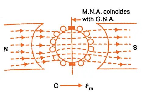
The above figure shows the flux due to main poles (main flux) when the armature conductors carry no current.
The flux across the air gap is uniform. The m.m.f. producing the main flux is represented in magnitude and direction by the vector OFm in fig (i). Note that OFm is perpendicular to GNA.
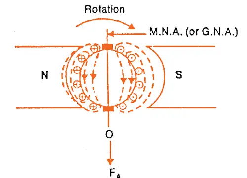
This shows the flux due to the current flowing in armature conductors of dc generator alone (main poles unexcited).
The armature conductors to the left of GNA. carry current “in” (×) and those to the right carry current “out” (•). The direction of magnetic lines of force can be found by corkscrew rule.
It is clear that armature flux is directed downward parallel to the brush axis. The MMF producing the armature flux is represented in magnitude and direction by the vector OFA.
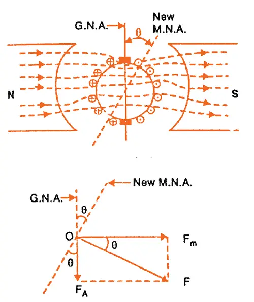
It shows the flux due to the main poles and that due to the current in armature conductors acting together. The resultant MMF OF is the vector sum of OFm and OFA as shown in fig (iii).
Since MNA is always perpendicular to the resultant MMF, the MNA is shifted through an angle θ. Note that MNA is shifted in the direction of rotation of the generator.
In order to achieve sparkless commutation, the brushes must lie along the MNA. Consequently, the brushes are shifted through an angle θ so as to lie along the new MNA as shown in figure below.
Due to the brush shift, the MMF FA of the armature is also rotated through the same angle θ. It is because some of the conductors which were earlier under N-pole now come under S-pole and vice-versa.
The result is that armature MMF FA will no longer be vertically downward but will be rotated in the direction of rotation through an angle θ as shown in the figure. Now FA can be resolved into rectangular components Fc and Fd.
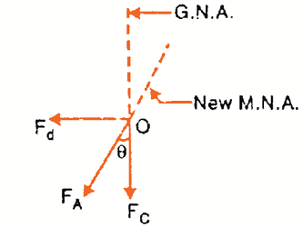
The component Fd is in direct opposition to the MMF OFm due to main poles. It has a demagnetizing effect on the flux due to main poles. For this reason, it is called the demagnetizing or weakening component of armature reaction in dc machines.
The component Fc is at right angles to the MMF OFm due to main poles. It distorts the main field. For this reason, it is called the cross magnetizing or distorting component of armature reaction in dc machines.
It may be noted that with the increase of armature current, both demagnetizing and distorting effects will increase.
Factors Influencing Armature Reaction
Several factors influence the magnitude and direction of armature reaction:
- Armature Current: The strength of the armature reaction is directly proportional to the armature current. Higher currents lead to stronger armature reactions.
- Field Winding Design: The design of the field winding and the placement of the field magnets in relation to the armature also influence armature reaction.
- Direction of Armature Current: The direction of the armature current in relation to the field magnets’ magnetic flux determines whether the armature reaction enhances or opposes the main field.
Effects of Armature Reaction on Generator Performance
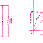
Understanding armature reaction is essential because it can significantly affect a DC generator’s performance. Some of the key impacts include:
- Voltage Control: Armature reaction can be harnessed to help control the output voltage of the generator, a critical factor in many applications.
- Commutation and Brush Wear: Misalignment of the neutral plane due to armature reaction can lead to poor commutation, causing sparking, brush wear, and reduced generator efficiency.
- Efficiency and Load Regulation: Proper management of armature reaction is crucial for maintaining generator efficiency and ensuring that it operates reliably under varying load conditions.
Compensating for Armature Reaction
As we’ve uncovered in the previous section, armature reaction in DC generators can introduce complexities that impact performance and efficiency. However, engineers have developed various strategies and mechanisms to mitigate and compensate for these effects, ensuring the reliable operation of DC generators. In this section, we will delve into these methods.
A. Methods to Mitigate Armature Reaction
- Interpoles: Interpoles, also known as commutating poles, are additional sets of field poles strategically placed between the main field poles. These interpoles generate a compensating magnetic field that counteracts the armature reaction, helping to maintain a more stable magnetic field.
- Compensating Windings: In some DC generators, compensating windings are added to the armature core. These windings produce a magnetomotive force (MMF) that opposes the armature reaction’s effects, stabilizing the magnetic field.
- Pole Shifting: In certain generator designs, the position of the field poles can be adjusted to counteract the distortion caused by armature reaction. This method allows for precise control over the magnetic field.
B. Brush Positioning and Commutation Adjustments
Proper brush positioning and commutation adjustment play a critical role in managing armature reaction:
- Neutral Plane Adjustment: Engineers can adjust the neutral plane, where the induced voltage in the armature coil is zero, by changing the position of the brushes. This ensures that commutation occurs smoothly and minimizes sparking and brush wear.
- Brush Material and Design: The choice of brush material and design affects the quality of commutation. High-quality brushes with appropriate materials reduce the impact of armature reaction.
C. Use of Interpoles and Compensating Windings
Interpoles and compensating windings are especially effective in large DC generators used in power plants, industrial applications, and traction systems. By implementing these technologies, engineers can optimize the generator’s performance under varying load conditions and maintain voltage stability.
Compensating for armature reaction is essential not only for the efficient operation of DC generators but also for extending their lifespan and minimizing maintenance requirements.

This is my first time pay a visit at here and i am genuinely pleassant to read everthing at single place.
the posts are very quick for beginners.
thank you