The three-phase induction motors are the most widely used electric motors in the industry. They work on the principle of electromagnetic induction.
Due to the similarity in the working principle of the transformer, it is also known as the rotating transformer.
They run at essentially constant speed from no load to full load. However, the speed is frequency-dependent and consequently, these motors are not easily adapted to speed control.
We usually prefer DC motors when large speed variations are required.
Let’s understand the construction of a three-phase induction motor before learning the working principle.
Construction of Three Phase Induction Motor
Like any electric motor, a 3-phase induction motor has a stator and a rotor. The stator carries a 3-phase winding (called stator winding) while the rotor carries a short-circuited winding (called rotor winding).
Only the stator winding is fed from the 3-phase supply. The rotor winding derives its voltage and power from the externally energized stator winding through electromagnetic induction and hence the name.
A 3-phase induction motor has two main parts
- Stator
- Rotor
The rotor is separated from the stator by a small air-gap which ranges from 0.4 mm to 4 mm, depending on the power of the motor.
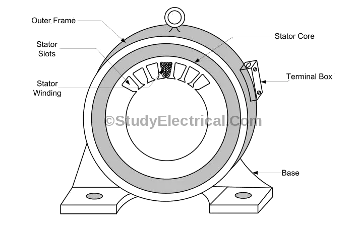
1. Stator of 3-Phase Induction Motor
The stator consists of a steel frame that encloses a hollow, cylindrical core made up of thin laminations of silicon steel to reduce hysteresis and eddy current losses.
A number of evenly spaced slots are provided on the inner periphery of the laminations. The insulated conductors are connected to form a balanced 3-phase star or delta connected circuit.
The 3-phase stator winding is wound for a definite number of poles as per the requirement of speed. Greater the number of poles, lesser is the speed of the motor and vice-versa.
When 3-phase supply is given to the stator winding, a rotating magnetic field of constant magnitude is produced. This rotating field induces currents in the rotor by electromagnetic induction.
2. Rotor of 3-Phase Induction Motor
The rotor, mounted on a shaft, is a hollow laminated core having slots on its outer periphery. The winding placed in these slots (called rotor winding) may be one of the following two types:
- Squirrel Cage Type
- Wound Rotor Type
Working Principle Three Phase Induction Motor
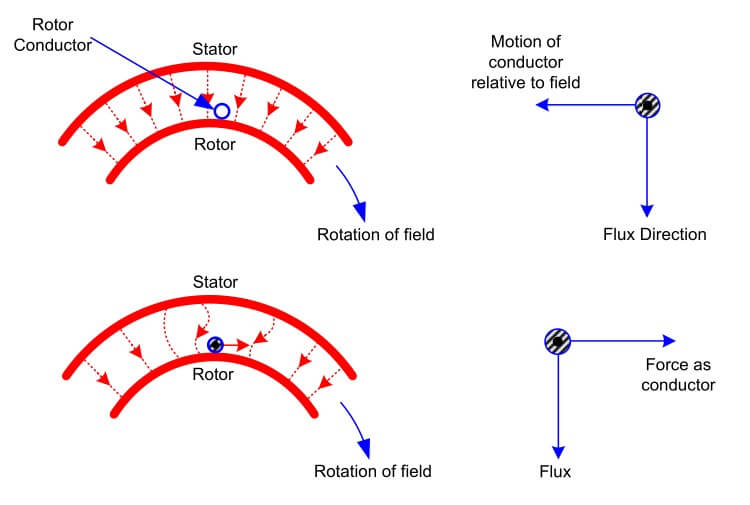
For explaining the principle of operation of a three-phase induction motor, consider a portion of the three-phase induction motor as shown in the figure.
The working of the three-phase induction motor is based on the principle of electromagnetic induction.
When three-phase stator winding of an induction motor is energized from a 3 phase supply, a rotating magnetic field is set up which rotates around the stator at synchronous speed (Ns).

Synchronous Speed,
Ns = 120 f/P
Where,
f = frequency
P = Number of Poles
(For more details about rotating magnetic field, read Production of rotating magnetic field).
This rotating field passes through the air gap and cuts the rotor conductors, which are stationary.
An EMF gets induced in every rotor conductor due to the relative speed between the rotating magnetic flux and the stationary rotor. Since the rotor circuit is short-circuited, currents start flowing in the rotor conductors.
The current-carrying rotor conductors are placed in the magnetic field produced by the stator. Consequently, a mechanical force acts on the rotor conductors. The sum of the mechanical forces on all the rotor conductors produces a torque which tends to move the rotor in the same direction as the rotating field.
The fact that the rotor is urged to follow the stator field (i.e., rotor moves in the direction of stator field) can be explained by Lenz’s law.
According to Lenz’s law, the direction of rotor currents will be such that they tend to oppose the cause of producing them.
Now, the cause producing the rotor currents is the relative speed between the rotating field and the stationary rotor conductors.
Hence to reduce this relative speed, the rotor starts running in the same direction as that of the stator field and tries to catch it. This is how a three-phase induction motor starts running.
Slip in Induction Motor
We have seen above that the rotor rapidly accelerates in the direction of the rotating magnetic field.
In practice, the rotor can never reach the speed of stator flux. If it did, there would be no relative speed between the stator field and rotor conductors, no induced rotor currents and, therefore, no torque to drive the rotor.
The friction and windage would immediately cause the rotor to slow down. Hence, the rotor speed (N) is always less than the stator field speed (Ns). This difference in speed depends upon load on the motor.
The difference between the synchronous speed Ns of the rotating stator field and the actual rotor speed N is called slip in a three-phase induction motor.
Slip is usually expressed as a percentage of synchronous speed i.e.,
Slip, s = (Ns – N)/Ns × 100 %
The quantity N s – N is sometimes called slip speed.
When the rotor is stationary (i.e., N = 0), slip, s = 1 or 100 %.
In an induction motor, the change in slip from no-load to full-load is hardly 0.1% to 3% so that it is essentially a constant-speed motor.
Comments are closed.