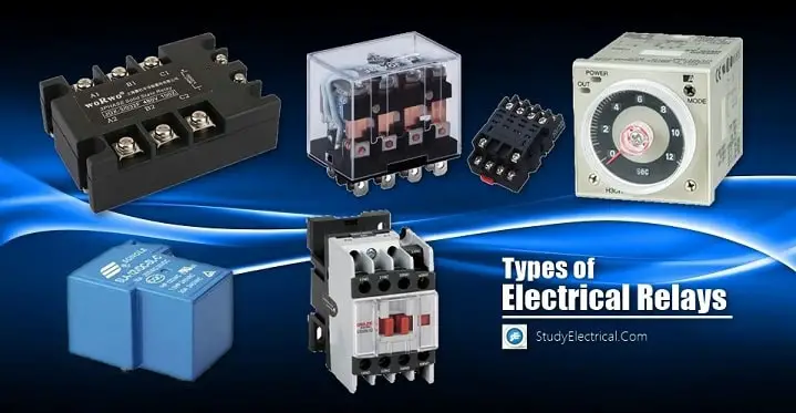
We have already discussed the working of electrical relays. Now we are going through different types of electrical relays.
There are two basic classifications of relays:
- Electromechanical Relays
- Solid State Relays
One main difference between them is electromechanical relays have moving parts, whereas solid state relays have no moving parts. In addition to them there are different types of protective relays available in the industry.
Read more about Different Types of Protective Relays and Function of Protective Relays.
Electromechanical Relays
Electromechanical relays are switches that typically are used to control high power electrical devices.
Electromechanical relays are used in many of today’s electrical machines when it is vital to control a circuit, either with a low power signal or when multiple circuits must be controlled by one single signal.
Advantages of Electromechanical relays include lower cost, no heat sink is required, multiple poles are available, and they can switch AC or DC with equal ease.
Some of the electromechanical relays are
- general purpose relays,
- power relay,
- contactor and
- time delay relay.
Each of them are briefly explained here.
General Purpose Relay
The general-purpose relay is rated by the amount of current its switch contacts can handle. Most versions of the general-purpose relay have one to eight poles and can be single or double throw.

General Purpose Relays are cost-effective 5-15 Amp switching devices used in a wide variety of applications. These are found in computers, copy machines, and other consumers electronic equipment and appliances.
Typical Applications: Lighting controls, time delay controls, industrial machine controls, energy management systems, control panels, forklifts, HVAC.
Power Relay
The power relay is capable of handling larger power loads 10-50 amperes or more. They are usually single-pole or double-pole units.

Power relays also contain an armature, a spring and one or several contacts. If the power relay is designed to normally be open, when power is applied, the electromagnet attracts the armature, which is then pulled in the coil’s direction until it reaches a contact, therefore closing the circuit.
If the relay is designed to be normally closed, the electromagnetic coil pulls the armature away from the contact, therefore opening the circuit.Power relays are used for many different applications, including:
- Automotive electronics
- Audio amplification
- Telephone systems
- Home appliances
- Vending machines
Power relays are used for switching a wide variety of currents for applications including everything from lighting control to industrial sensors.
Contactor
A special type of high power relay, it’s used mainly to control high voltages and currents in industrial electrical applications. Because of these high power requirements, contactors always have double-make contacts.
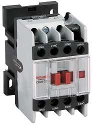
These relays are switchgear devices for control and auxiliary circuits and are used to control, provide signals and interlock switching devices and switchgear panels.
A contactor is a large relay, usually used to switch current to an electric motor or other high-power loads. Large electric motors can be protected from overcurrent damage through the use of overload heaters and overload contacts.
If the series-connected heaters get too hot from excessive current, the normally-closed overload contact will open, de-energizing the contactor sending power to the motor.
Time-Delay Relay
The contacts might not open or close until some time interval after the coil has been energized. This is called delay-on-operate.
Delay-on-release means that the contacts will remain in their actuated position until some interval after the power has been removed from the coil.

A third delay is called interval timing. Contacts revert to their alternate position at a specific interval of time after the coil has been energized.
The timing of these actions may be a fixed parameter of the relay, or adjusted by a knob on the relay itself, or remotely adjusted through an external circuit.
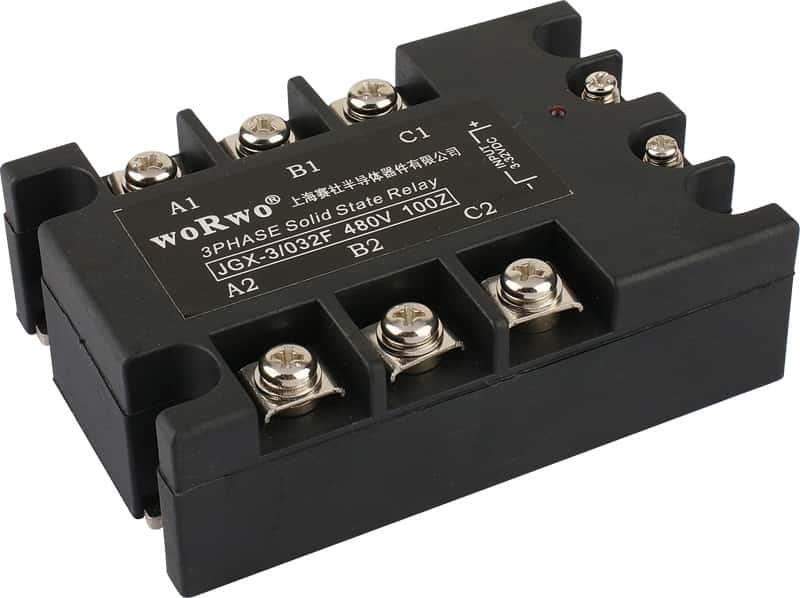
Solid State Relays
A solid-state relay (SSR) is an electronic switching device that switches on or off when a small external voltage is applied across its control terminals.
SSRs consist of a sensor which responds to an appropriate input (control signal), a solid-state electronic switching device which switches power to the load circuitry, and a coupling mechanism to enable the control signal to activate this switch without mechanical parts.
The relay may be designed to switch either AC or DC to the load. It serves the same function as an electromechanical relay, but has no moving parts. The figure below shows a three phase solid state relay.
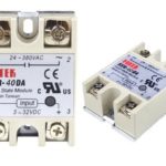
How Solid State Relay Works?
These active semiconductor devices use light instead of magnetism to actuate a switch. The light comes from an LED, or light emitting diode. When control power is applied to the device’s output, the light is turned on and shines across an open space.
On the load side of this space, a part of the device senses the presence of the light, and triggers a solid state switch that either opens or closes the circuit under control.
- Advantages of Solid State Relays include low EMI/RFI, long life, no moving parts, no contact bounce, and fast response.
- The drawback to using a solid state relay is that it can only accomplish single pole switching.


Should Relay’s be fixed first to the incomer cable before Circuit Breaker’s follows then next should be Conductor’s to the Motors?
Please read Working of protective relays here: https://studyelectrical.com/2015/08/how-protective-electrical-relays-work.html
It is explained there.