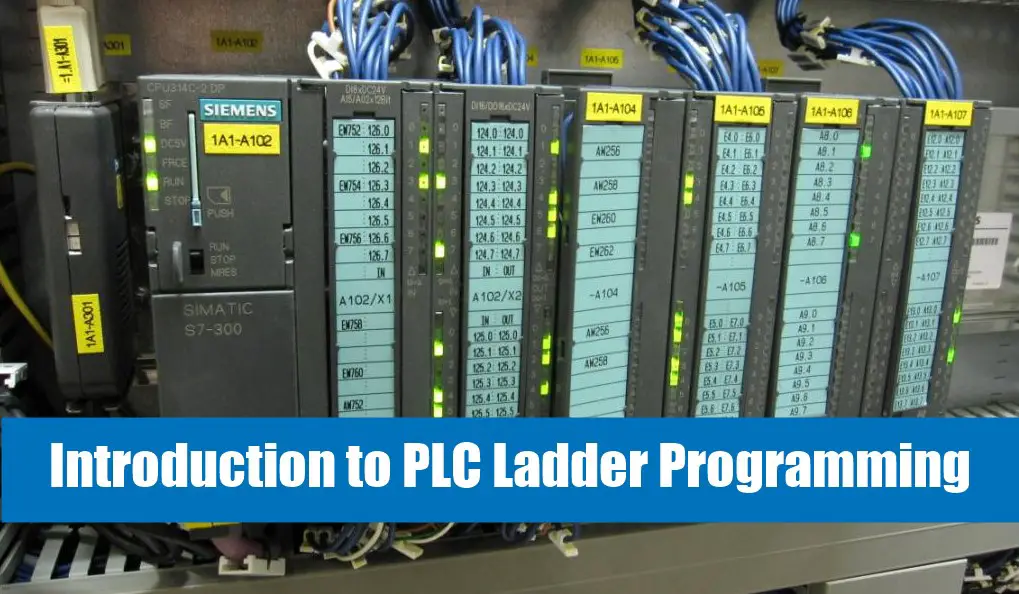
We have already discussed the introduction to programmable logic controllers. Please go through it before reading this. In this article, we will give you a brief introduction to programming PLC using the ladder diagram.
We can also use assembly language based on the mnemonics, e.g. LD is used to indicate the operation required to load the data that follows the LD, and a computer program called an assembler is used to translate the mnemonics into machine code.
Programming can be made even easier by the use of the so-called high-level languages, e.g. C, BASIC, PASCAL, FORTRAN, COBOL. These use pre-packaged functions, represented by simple words or symbols descriptive of the function concerned. For example, with C language the symbol & is used for the logic AND operation.
However, the use of these methods to write programs requires some skill in programming and PLCs are intended to be used by engineers without any great knowledge of programming. As a consequence, ladder programming was developed.
Ladder Programming is a means of writing programs which can then be converted into machine code by some software for use by the PLC microprocessor.
This method of writing programs became adopted by most PLC manufacturers, however, each tended to have developed their own versions and so an international standard has been adopted for ladder programming and indeed all the methods used for programming PLCs.
Ladder diagrams
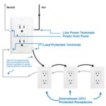
As an introduction to ladder diagrams, consider the simple wiring diagram of an electrical circuit shown below,

The diagram shows the circuit for switching on or off an electric motor. We can redraw this diagram in a different way, using two vertical lines to represent the input power rails and stringing the rest of the circuit between them.

Both circuits have the switch in series with the motor and supplied with electrical power when the switch is closed. The circuit shown above is termed a ladder diagram.
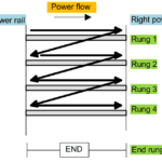
In a ladder diagram, the power supply for the circuits is always shown as two vertical lines with the rest of the circuit as horizontal lines.
- The power lines, or rails as they are often termed, are like the vertical sides of a ladder with the horizontal circuit lines like the rungs of the ladder.
- The horizontal rungs show only the control portion of the circuit, in the case shown in the figures above, it is just the switch in series with the motor.
- Circuit diagram often shows the relative physical location of the circuit components and how they are actually wired.
- With ladder diagrams, no attempt is made to show the actual physical locations and the emphasis is on clearly showing how the control is exercised.
Ladder Diagram Example

This figure shows an example of a ladder diagram for a circuit that is used to start and stop a motor using push buttons.
- In the normal state, push button 1 is open and push button 2 closed.
- When button 1 is pressed, the motor circuit is completed and the motor starts. Also, the holding contacts wired in parallel with the motor close and remain closed as long as the motor is running.
- Thus when the push button 1 is released, the holding contacts maintain the circuit and hence the power to the motor.
- To stop the motor, button 2 is pressed. This disconnects the power to the motor and the holding contacts open.
- Thus when push button 2 is released, there is still no power to the motor.
Thus we have a motor which is started by pressing button 1 and stopped by pressing button 2.
Next: What is a ladder diagram and How to draw a Ladder Diagram?